Upperside World Congress 2026 - Time Synchronization Demonstration
As a final step, we prepared a testbed setup that included our crucial findings and tests executed over two weeks, combining multiple test cases from the Time Synchronization test area into a single setup and network, showcasing the culmination of all our testing efforts and true interoperability.
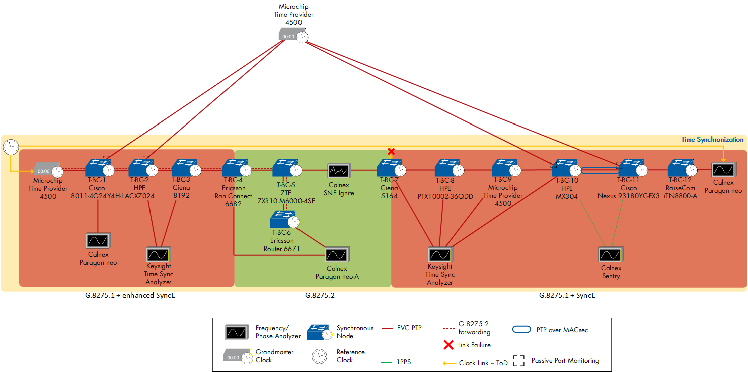
Figure 100: Time Synchronization Demonstration - Test bed setup
The setup consisted of one Telecom Grandmaster (T-GM) and 12 Telecom Boundary Clocks (T-BCs), 11 of which were cascaded in a chain; the T-BC that was not within the main chain served as the ITU-T G.8275.2 (Partial Timing Support; PTS) recipient of the forwarded PTS packets from the T-GM that is providing both FTS and PTS PTP messaging.
The first segment of the chain consisted of four T-BCs using the ITU-T G.8275.1 PTP profile (Full Timing Support; FTS) with enhanced synchronous Ethernet (eSyncE), with T-BC-4 serving as the interworking function (IWF) to translate from FTS to PTS.
The second segment of the chain consisted of three more T-BCs using PTS.
T-BC-5 was the direct client to the IWF node.
T-BC-6 served as the recipient of the forwarded PTS packets from the T-GM, showing StepsRemoved = 1 despite five other T-BCs being between the T-GM and T-BC-6.
T-BC-7 served a dual purpose, acting as the IWF node from PTS to FTS and also as an Assisted Partial Timing Support (APTS) node to the downstream T-BCs, with the link between T-BC-5 and T-BC-7 being impaired by introducing 12 µs of delay asymmetry using the Calnex SNE Ignite.
The third and last segment of the chain consisted of the remaining five T-BCs, T-BC-8 to T-BC-12, using FTS and synchronous ethernet (SyncE), with T-BC-8 as the direct node after the IWF and AFTS node. Additionally, PTP over MACsec was performed between T-BC-10 and T-BC-11.
Throughout the whole chain, T-BC-1, T-BC-2, T-BC-10, and T-BC-11 were performing Passive Port Monitoring and Performance Monitoring.
Every T-BC across the chain was connected to a Frequency/Phase Analyzer to measure their PTP output, using the Calnex Paragon neo, Paragon neo-A, or the Keysight Time Sync Analyzer, or their 1PPS output, using the Calnex Sentry.
The test started with all nodes upstream of T-BC-7 being locked to the T-GM and every node downstream of T-BC-7 being locked to T-BC-7 itself, as it was practically acting as a T-GM itself.
Then, the GNSS connection to the AFTS node was cut, causing the AFTS node to seamlessly switch to its backup PTP path originating from the T-GM, while compensating for 12 µs of delay asymmetry; no T-BC downstream lost lock during the switch-over.
Overall, this test was a great success. A max|TEL| of less than 100 ns was measured at the end of the chain, which is remarkable given all the T-BCs, IWFs, impairments, and other features. We were able to recreate a real-world-like setup, showcasing interoperability across a range of features needed and appreciated in a time-synchronized network.
| Telecom Grandmaster | Telecom Boundary Clocks | Frequency/Phase Analyzers | Impairment Emulator |
|---|---|---|---|
| Microchip Time Provider 4500 | Cisco 8011 HPE ACX 7024 Ciena 8192 Ericsson RAN Connect 6682 ZTE M6000-4SE Ericsson Router 6671 Ciena 5164 HPE PTX10002-36QDD Microchip Time Provider 4500 HPE MX 304 Cisco Nexus 93180YC-FX3 Raisecom iTN8800-A | Calnex Paragon neo Calnex Paragon neo-A Calnex Sentry Keysight Time Sync Analyzer | Calnex SNE Ignite |
Table 79: Upperside World Congress 2026 - Time Synchronization Demonstration - Devices Under Test
| < Previous | Next > |