Passive Port Monitoring
The optional Passive Port Monitoring (PPM) feature, as defined in Annex G of ITU-T G.8275.1, has demonstrated its value in the operation of synchronization networks. PPM can be utilized to monitor the Precision Time Protocol (PTP) phase/time difference between the passive port and the slave port of the Telecom Boundary Clock (T-BC) or Telecom Time Synchronous Clock (T-TSC), and is applicable in the following scenarios:
- Measuring and compensating for asymmetry within network nodes
- Monitoring and comparing the PTP phase/time differences between various clock sources across the network
- Continuously measuring the PTP phase/time difference between ports on a specific T-BC or T-TSC node from upstream time sources to help identify devices that affect clock quality.
To verify the functionality of this feature, we deployed a scenario with one Telecom Grandmaster (T-GM), one impairment emulator, two T-BCs, and a frequency/phase analyzer. If a real T-GM, the Microchip TimeProvider 4500 was used, then the Calnex SNE Ignite was used as the impairment emulator to produce an artificial delay;
If an emulated T-GM, like the Calnex Paragon neo, Paragon neo-A, or the Keysight Time Sync Analyzer, was used, then the impairment was directly applied by the emulated T-GM.
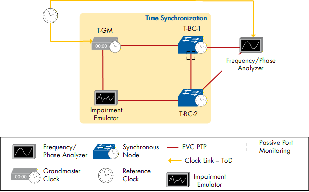
Figure 93: Passive Port Monitoring - general test bed setup
T-BC-1 and T-BC-2 were both locked to the T-GM and using it as their primary time reference, with the link between the T-GM and T-BC-2 being impaired. T-BC-2 was then acting as a Master towards T-BC-1’s passive port. Both T-BCs' output was then measured by a frequency/phase analyzer, either the Calnex Paragon neo, Paragon neo-A, or the Keysight Time Sync Analyzer.
The impairment emulator first introduced an asymmetric delay of +540 ns, followed by a -300 ns asymmetric delay. These delays induce a time error of +270 ns and -150 ns, respectively, on the downstream T-BC-2, since the time error on that node will be half of the introduced one-way delay. That offset should be measured on the passive port of T-BC-1.
Nine test combinations were performed, and all T-BC-1s properly displayed their PPM capabilities by measuring the +270 ns/-150 ns time offset relative to their primary time reference, the T-GM.
| Telecom Grandmaster | Telecom Boundary Clock - 1 with Passive Port Monitoring | Telecom Boundary Clock - 2 | Impairment Emulator | Frequency/Phase Analyzer |
|---|---|---|---|---|
| Keysight Time Sync Analyzer | Ericsson RAN Connect 6682 | Microchip Time Provider 4500 | Keysight Time Sync Analyzer | Keysight Time Sync Analyzer |
| Keysight Time Sync Analyzer | Microchip Time Provider 4500 | Ericsson RAN Connect 6682 | Keysight Time Sync Analyzer | Keysight Time Sync Analyzer |
| Keysight Time Sync Analyzer | ZTE ZXCTN 6120H-S | Ericsson Router 6676 | Keysight Time Sync Analyzer | Keysight Time Sync Analyzer |
| Microchip Time Provider 4500 | ZTE ZXCTN 6120H-E | Cisco 8011-4G24Y4H-I | Calnex SNE Ignite | Keysight Time Sync Analyzer |
| Keysight Time Sync Analyzer | Ericsson Router 6676 | ZTE ZXCTN 6120H-S | Keysight Time Sync Analyzer | Keysight Time Sync Analyzer |
| Microchip Time Provider 4500 | Cisco 8011-4G24Y4H-I | ZTE ZXCTN 6120H-E | Calnex SNE Ignite | Keysight Time Sync Analyzer |
| Calnex Paragon neo-A | HPE MX 304 | Ciena 5164 | Calnex Paragon neo-A | Calnex Paragon neo-A |
| Keysight Time Sync Analyzer | ZTE ZXR10 M6000-4SE | Ericsson Router 6671 | Keysight Time Sync Analyzer | Keysight Time Sync Analyzer |
| Keysight Time Sync Analyzer | Ericsson Router 6671 | ZTE ZXR10 M6000-4SE | Keysight Time Sync Analyzer | Keysight Time Sync Analyzer |
Table 72: Passive Port Monitoring - Test combinations
| < Previous | Next > |