Time Error Accumulation and Calculation for Class D Telecom Boundary Clocks
Synchronization networks in deployment often include chains of Telecom Boundary Clocks (T-BCs), each with established device and network time-error specifications.
This test case assessed the performance of such a chain based on the number of class D T-BCs it contained.
Class D T-BCs have only a single metric, max|TEL|, defined, for which the accumulation is not specified. max|TEL| may be considered as all constant Time Error (cTE), all dynamic Time Error low-pass filtered (dTEL), or a combination of the two. Considering all of the time error as cTE gives a limit of N · max|TEL|, i.e., N · 5ns, with N being the number of T-BCs in the chain, since the full allowance is linearly summed.
If considered only as dTEL, the limit could be calculated as √(N ∙ max|TEL|²), i.e, √(N ∙ 5ns²).
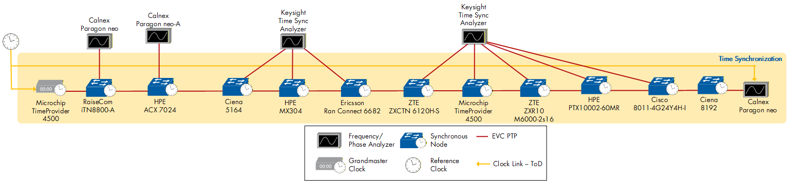
Figure 96: Time Error Accumulation and Calculation for a Class D T-BC chain - Test bed setup
In this test, the Microchip TimeProvider 4500 acted as the Telecom Grandmaster (T-GM), and eleven Class D T-BCs were included. Based on the formula, treating all time error as cTE, the limit was 55 ns.
The T-GM distributed PTP and SyncE downstream, with all T-BCs locked. Each T-BC was individually connected to a frequency/phase analyzer, either the Calnex Paragon-neo, Paragon neo-A, or Keysight Time Sync Analyzer.
This approach allowed us to observe both the total time error at the end of the chain and the time error contributed by each T-BC.
At the end of the chain, we measured a max|TEL| of 52.313 ns, meaning that we were within the above-mentioned limit of 55 ns.
Additionally, we measured the relative cTE between T-BC-1 and T-BC-11 (36.981 ns), as well as the relative low-pass-filtered dynamic Time Error (dTEL) between T-BC-1 and T-BC-11 (4.397 ns).
Analysing the 37 ns of cTE relative to T-BC-1 and T-BC-11 results in an average of around 3.5ns of cTE per T-BC in the chain. As per ITU-T G.8273.2, a class D T-BC is given a max|TEL| of 5 ns; since max|TEL| is the sum of cTE and dTEL, that would leave us with around 1.5 ns of dTEL per T-BC. The accumulated dTEL would then be, according to the formula above, √(11 ∙ 1.5 ns²) = 4.97 ns. Comparing this to the relative dTEL measured between T-BC-1 and T-BC-11 (4.4 ns), we are within that limit. Combining our measured cTE and dTE yields 42 ns of max|TEL| throughout the chain. An additional TE budget of around 10 ns can be attributed to a time-error contribution from the T-GM, resulting in the 52.313 ns measured at the end of the chain.
| Telecom Grandmaster | Telecom Boundary Clocks | Frequency/Phase Analyzers |
|---|---|---|
| Microchip Time Provider 4500 | Raisecom iTN8800-A HPE ACX 7024 Ciena 5164 HPE MX 304 Ericsson RAN Connect 6682 ZTE ZXCTN 6120H-S Microchip Time Provider 4500 ZTE ZXR10 M6000-2S16 HPE PTX10002-60MR Cisco 8011-4G24Y4H-I Ciena 8192 | Calnex Paragon neo-A Calnex Paragon neo Keysight Time Sync Analyzer |
Table 76: Time Error Accumulation and Calculation for Class D Telecom Boundary Clocks - Devices Under Test
| < Previous | Next > |