1.1- POD Requirement Analysis and Design Generation
The first step in deploying a DC POD is to define the physical structure and create a parameter plan for the underlay network. In this test, we delegated this task to the iMaster NCE-Fabric. The NCE-Fabric gathered the user's intent, including the number of spine switches, server leaf nodes, border leaf nodes, and the security service as an on/off switch. Following the TM Forum and ETSI ENI standards, this "intent" stage does not involve communication between the NCE-Fabric and the network devices, so at this point, all routers and switches are still turned off.
The intent we defined included four server leaf nodes, two spine switches, two border leaf nodes, and enabled the security service switch. The NCE-Fabric processed this intent and recommended a physical topology with all devices connected properly according to the spine-leaf architecture, as depicted in Figure 1.
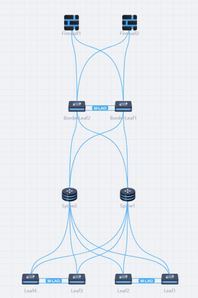
Figure 1: Proposed POD Topology by NCE-Fabric
In addition to the physical design, the NCE-Fabric also suggested hostnames, a management IP address pool, VTEP IP addresses, VTEP MAC addresses, BGP router IDs, link IP addresses for the connections between the network nodes, and recommended using OSPF and BGP for routing. All proposed settings were presented for user review.
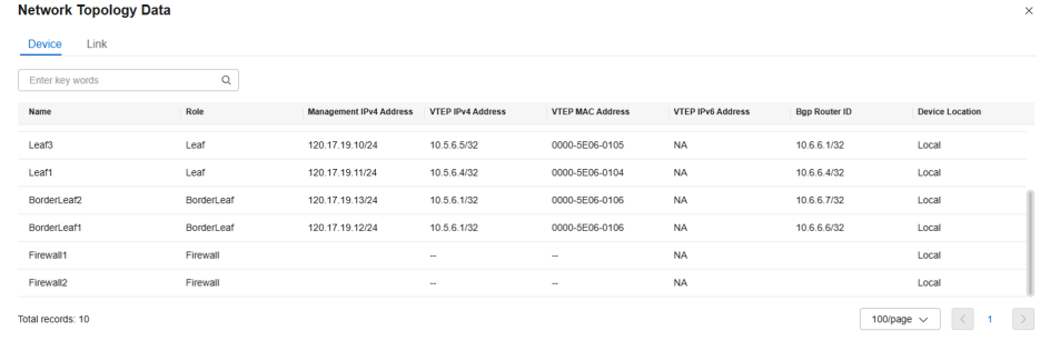
Figure 2: Recommended Device Parameters by NCE-Fabric
The suggested parameters, including the intent itself, were editable and could be adjusted by the user. This allowed for customization to fit specific IP schemes or other user-specific requirements. We tested this by modifying the intent after generating the initial network plan, specifically changing the number of server leaf nodes from four to six.
The NCE-Fabric accepted the updated intent and adjusted the topology accordingly. It then rechecked whether the existing parameters were still valid for the new design. As a result, the user needed to update some parameters. For example, the management IP pool did not contain enough addresses to support the two additional nodes.
Since this was still the first step in defining the POD design, the simplest solution was to reenter the updated intent from scratch and generate a new parameter set and network design. In contrast, editing individual parameters such as IP addresses or VTEP settings worked without issues, as long as the new values were compatible with the design.
After the user reviewed the generated parameters, the NCE-Fabric proceeded to create configuration files for each network device in the POD. These files are CLI scripts defined to match each device's specific role and configuration. The scripts include all required configurations, such as interface configurations, IP addresses, routing protocols, and other parameters previously defined during the planning phase. Figure 3 shows a snippet from one of the configuration scripts generated by the NCE-Fabric.
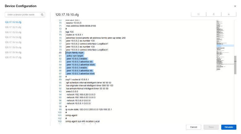
Figure 3: Configuration Script Generated by NCE-Fabric for a Network Node
The results achieved in this test confirm that the NCE-Fabric meets the Level 4 criteria for the capabilities POD requirement analysis and automated network design generation, according to the requirements for DC POD planning and provisioning defined in ETSI GR ENI 049.
| < Previous | Next > |