2.3- Application Scheme Simulation and Decision-Making
The applications' configurations have been created in NCE-Fabric but have not yet been delivered to the network devices. At this point, running a simulation is helpful and provides the user with insight into the expected changes and the behavior of the applications once deployed. NCE-Fabric supports application simulation and analyzes the results from multiple perspectives.
We ran the simulation for App3's configurations. NCE-Fabric provided a detailed simulation report that includes the logical services and entities that will be created in the network, along with descriptions indicating which logical instances will be used to deploy each service.
The simulation report confirmed a successful creation of all required logical components, including logic networks, logic routers, switches, and external connectivity elements. Each resource was marked with a "Success" execution status, indicating that the planned configuration passed the validation, as shown in Figure 16.
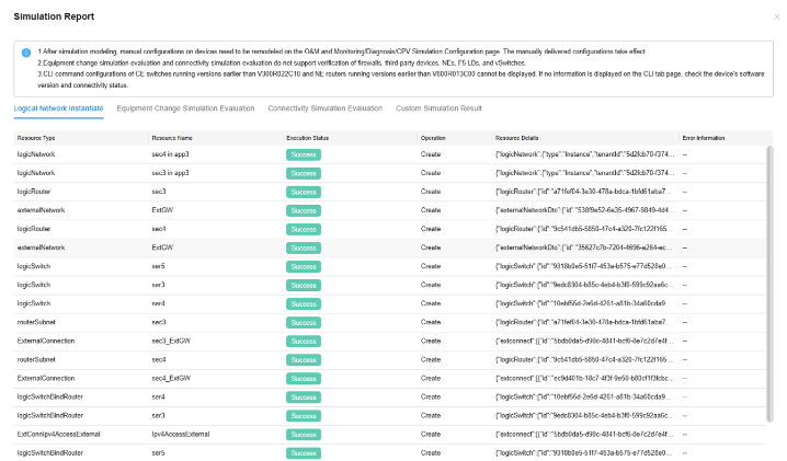
Figure 16: Simulation Report - Logical Network Instantiate
The simulation report also included detailed information about device configuration changes and resource consumption resulting from the application deployment. This data helps verify whether each device in the fabric can support the required configuration without exceeding resource limits.
The report showed parameters such as the number of VRFs, static routes, Layer 2 sub-interfaces, and VNI/BD/EVPN entries per device. As shown in Figure 17, both current consumption and expected usage after deployment were listed.
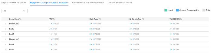
Figure 17: Simulation Report - Equipment Change Simulation Evaluation
The device entries shown in the previous figure can also be expanded to display the exact configuration changes that will be applied. This information is available in CLI and NETCONF formats, allowing for a granular verification level.
Under the Connectivity Simulation Evaluation tab, NCE-Fabric checked the reachability between IP addresses assigned to the subnets defined in the application services. The simulation listed eight source-destination pairs associated with specific devices and interfaces. All entries were marked as "Reachable," indicating that the simulated configuration is supposed to work as expected.
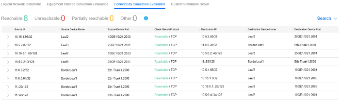
Figure 18: Simulation Report - Connectivity Simulation Evaluation
The entries in the previous figure can be expanded to display all possible paths between each pair of IP addresses. These paths typically differ in the intermediate hops.
The Connectivity Simulation Evaluation can also be customized. The user may specify any two IP addresses, and NCE-Fabric will simulate and validate the connectivity between them and generate a report similar to the one shown previously in Figure 18.
We then ran simulations for App1 and App2, including their inter-application connectivity. The simulation output followed the same structure format as the App3 results, while reflecting the specific design of App1 and App2. NCE-Fabric provided a detailed view of the logical components to be instantiated, the configuration changes on the relevant devices, and the expected resource consumption. In addition, the connectivity simulation confirmed that the defined communication path between App1 and App2 was reachable.
To evaluate the simulation's ability to detect potential issues in the services to be deployed, we emulated interface failure scenarios on the links between Leaf2 and both spine switches. This was done in two ways: first, by shutting down the physical interfaces on the device using CLI, and second, by removing the corresponding links within the NCE-Fabric user interface. In both cases, NCE-Fabric detected the disruption and marked the paths between the service endpoints on Leaf2 and those on Leaf3 and Leaf4 as unreachable, as shown in Figure 19.
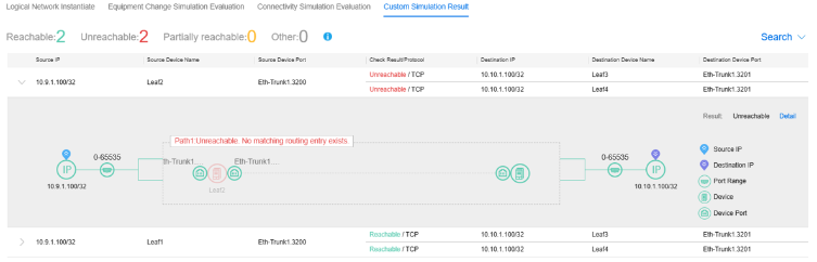
Figure 19: Simulation Report - Connectivity Results with Link Failure
The results of the previous and current tests demonstrated that NCE-Fabric supports the recommendation of network configurations for application provisioning, combined with detailed simulation and failure detection. This aligns with the Level 4 requirements for the Solution Generation capability, as defined in ETSI GR ENI 049.
| < Previous | Next > |